Recently, our company's engineers found that the traditional machining process of the steering rack eccentric cover parts in the existing steering assembly was still inadequate.
Therefore, I interviewed our company's very experienced engineer, Dai Xiong, and asked him how to optimize the relevant machining process route? His design produced the corresponding automated high-precision self-rotating eccentric tooling, which greatly improved the machining rate of eccentric cover parts, reduced the labor intensity of operators for secondary clamping, and gained significant economic benefits for our company.

Dai Xiong
1 What are steering rack eccentric cover parts?
Many eccentric cover-type parts are used in the automotive steering assembly, and the structure of most eccentric cover-type parts is shown in Figure 1. In order to improve the compactness of the structure, the inner hole and outer circle are designed with a certain amount of eccentricity, and the tolerance requirement is generally ±0.025mm. at present, it is common to use a CNC lathe to process the outer circle and inner hole by the process. Due to the large positioning error of the old machining process, it is difficult to ensure the design requirement of ±0.025mm tolerance during mass production.
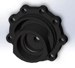
Eccentric cover parts structure schematic
2 Steering rack eccentric cover machining process
The old machining process of eccentric cover is as follows: rough and fine turning outer circle → drilling mounting hole → countersinking mounting hole boss → rough and fine turning inner hole → drilling and tapping tail hole → final inspection. In mass production, this process requires two sets of tooling to process the outer circle and inner hole on two CNC lathes respectively. Due to the existence of secondary clamping of the workpiece, repeated positioning produces cumulative errors, so the eccentricity of the part cannot reach the high design requirements. To improve the machining accuracy and adapt to the increasing quality requirements, it is necessary to reduce the accumulated errors.
The new process is designed as follows: drilling mounting holes → countersinking mounting hole tabs → rough and finish turning outer and inner holes → drilling and tapping tail holes → final inspection. The new process combines the two processes of rough turning, finishing turning of outer and inner holes into one tooling, which is completed in one clamping to reduce the errors caused by repeated positioning. At present, within the automotive processing industry, there is also the use of rotary jigs for machining eccentric work on CNC lathes.
However, it is common to use a manual rotary jig to process eccentric, and it is necessary to stop the manual rotary jig to adjust the eccentric after finishing the outer circle, so the processing efficiency is low, which is not conducive to the production requirements of high volume and high precision.
3 Steering rack eccentric cover tooling and processing method
According to the production process, the self-rotating eccentric tooling shown in Figure 2 is designed and produced, mainly consisting of 16 parts.
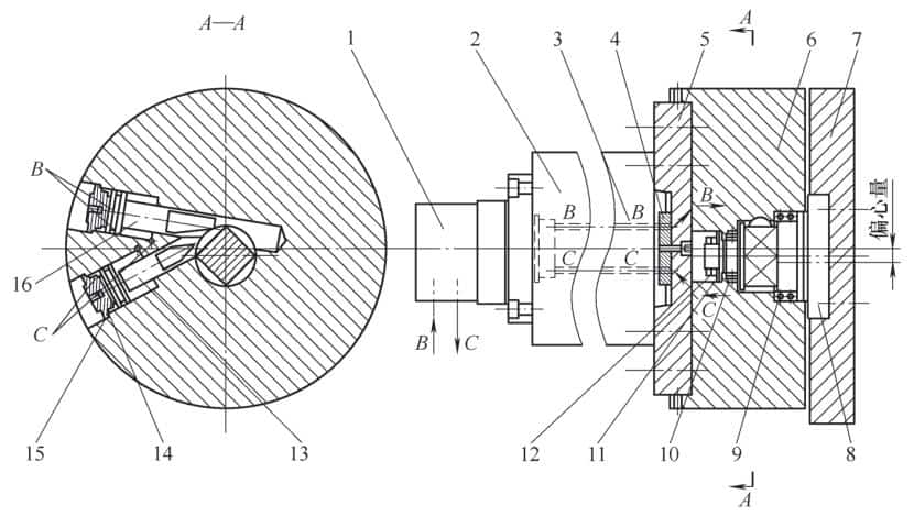
1 - Machine tool oil distributor 2 - Machine tool spindle 3 - Steel oil pipe 4 - Oil distribution flange 5 - Transition plate 6 - Rotating hydraulic cylinder 7 - Clamp specific 8 -Rotary shaft 9, 10-Angular contact ball bearing 11-Planar needle roller bearing 12-Lock master 13, 16-Piston 14-Hydraulic cylinder cover 15-Bore retaining ring
The machining method is as follows:
- The drilling and tapping center is used to machine the mounting holes and mounting hole tabs of the eccentric cover parts,
- Two pins on one side are used to locate the parts and clamp them on the self-rotating eccentric work holding specific 7, which is mounted on the CNC lathe spindle. The high-pressure oil of the machine tool enters the machine tool oil distributor 1 through the B oil circuit or C oil circuit as shown by the arrow in Fig. 2, flows through the steel oil pipe 3 installed in the machine tool spindle 2 to reach the oil distribution flange 4 and is distributed to the two pistons in the rotating hydraulic cylinder 6 through the transition plate 5, which are piston 16 and piston 13 respectively. hydraulic cylinder cover 14 and hole are sealed with retaining ring 15 to the outer chamber of the hydraulic cylinder, and when the CNC lathe program issues a command, the high-pressure oil is firstly fed through the B oil circuit, while the C oil circuit is returned to push piston 16 to move in the axial direction and pivot rotary axis 8 to rotate 45° through the bevel at the front of piston 16.
- The hydraulic station delay relay signals the C oil inlet and B oil return, and the piston 16 returns while the piston 13 moves toward the axis, and the piston 13 pivots the rotary axis 8 by 45° at the front of the piston, completing a cycle to achieve 90° rotation of the rotary axis 8. When the machine program issues the command again, the rotary axis 8 drives the clamping body 7 to complete the 180° rotation of the eccentric fixture, and at the same time, the eccentric cover parts are locked by the action of the bevel at the front of the piston 13. The rotary axis 8 is positioned by angular contact ball bearings 9 and 10, plane needle roller bearings 11, and locking master 12, which effectively ensures the rotary accuracy and load-bearing capacity of the rotary axis 8, thus realizing the function of machining the eccentric bore of the part by self-rotating eccentric tooling.
The whole process only needs one clamping, compact structure, reliable performance, high centering accuracy, and automatic rotation can be realized by the machine program without stopping, high processing efficiency, and can meet the requirements of high precision eccentric machining.
4 Economic analysis of the new process
The new machining process has achieved a significant improvement in product quality through the application of automated and high-precision tooling. The eccentricity tolerance of the machined parts is improved from ±0.025mm to ±0.015mm. 4 machine tools are used in the old machining process, and 4 machine tools are also used in the new process, but the production speed is significantly improved. The production bottleneck of the original machining process is in the rough turning and finishing turning inner hole process, which takes 248 s. Through process optimization, the two processes of rough turning, finishing turning outer circle and inner hole are compounded, and the bottleneck process is balanced by using 2 machine tools while reducing According to the monthly output of 30,000 pieces, 8 hours per shift and two shifts, the monthly processing volume of one production line of the old processing technology = 8×3600÷248×2×28 pieces = 6503 pieces, and the monthly processing volume of one production line of the new processing technology = 8×3600÷152×2×28 pieces = 10610 pieces.
Both sides reached the following consensus through several technical exchanges.
- As long as the technical requirements of the product drawing specify the standard used, the product conformity evaluation should be based on the technical standard of the product drawing, no matter which measuring equipment or evaluation software is used.
- The minimum envelope area should be included with reference to the theoretical curve, so the minimum envelope area should be equal to 2 times the maximum deviation. If the evaluation result is "maximum deviation minus minimum deviation or the sum of maximum deviation and minimum deviation", it is a "deviation fluctuation range" and cannot be used to evaluate whether the product is qualified or not.
- The technical requirements of the product clearly state that the geometric tolerance is in accordance with ISO standards. Therefore, the evaluation method of lip profile is unified as 2 times the maximum deviation, and the measurement result should be rectified if it exceeds the deviation. The supplier corrected the tooling according to the measurement results, and the measurement results of the lip profile of the improved main bearing are shown in Table 3, and randomly selected parts of the improved batch were tested, and all the profile degrees of the D part of the lip were qualified. The measuring equipment is HOMMEL T8000. Through several exchanges between supply and demand, rectification, optimization of manufacturing tooling, solidification of process parameters, unification of the main bearing cover lip profile measurement evaluation methods, and other measures, the monitoring plan was optimized to ensure the conformity of the product before mass production and played a quality prevention role. In the 5 years of mass supply of this product, no quality accident has occurred and the reputation of the whole product has been improved.
Table 3 Sampling results of lip tooth profile of the main bearing after improvement (Unit: mm)
| No.1 main bearing cover | No.1 main bearing cover | No.1 main bearing cover | No.2 main bearing cover | No.2 main bearing cover | No.2 main bearing cover | |
|---|---|---|---|---|---|---|
| Measurement site | Left | Middle | Right | Left | Middle | Right |
| Contour tolerance | 0.2 | 0.1 | 0.2 | 0.2 | 0.1 | 0.2 |
| 1(D-D) | 0.0069 | 0.0814 | 0.0081 | 0.0066 | 0.074 | 0.0086 |
| 2(Z) | 0.1101 (tolerance 0.2) | 0.1101 (tolerance 0.2) | 0.1101 (tolerance 0.2) | 0.1214 (tolerance 0.2) | 0.1214 (tolerance 0.2) | 0.1214 (tolerance 0.2) |
| 3(D-D) | 0.008 | 0.0972 | 0.0104 | 0.0101 | 0.0755 | 0.0102 |
| 4(D-D) | 0.0095 | 0.081 | 0.0064 | 0.0092 | 0.0847 | 0.0105 |
| 5(Z) | 0.0898(tolerance 0.2) | 0.0898(tolerance 0.2) | 0.0898(tolerance 0.2) | 0.0942(tolerance 0.2) | 0.0942(tolerance 0.2) | 0.0942(tolerance 0.2) |
| 6(D-D) | 0.0107 | 0.0676 | 0.0069 | 0.0081 | 0.0868 | 0.0106 |
5 Concluding remarks of Dai Xiong
With the rapid development of China's automobile manufacturing industry, the traditional contour measurement methods such as sample method, projection method, and profiling method cannot meet the needs of modern automobile parts production due to the low measurement accuracy and measurement efficiency. Two coordinate, three coordinate measuring machines and linear profilers,s and other digital inspection equipment are widely used to open up the idea of measuring and assessing the contour degree of auto parts, which has become the main means of controlling the geometric tolerance of auto parts products.
References
[1] Mechanical Designer's Handbook [M]. Mechanical Industry Press , edited by Wu Zongze, 2002
(We do not share your data with anybody, and only use it for its intended purpose)
The Previous Articles:
What Is Rack and Pinion Bushing? How To Tell If Rack and Pinion Bushings Are Bad?
Why Steering Rack Makes Noise When Turning?
How To Rebuild A Steering Rack?
What Is A Rotary Valve Power Steering Rack?
Rack And Pinion System Vs Power Steering System: What Are The Differences?
Power Steering Rack Market Analysis Report (Japan Market)
What Causes Steering Rack to Go Bad?
Design Of Car Rack And Pinion Steering Racks
What Is The Intelligent Steering Rack Used By VW, Toyota, Honda And Renault?


Leave A Comment