In the design and development of FSAE racing cars, the steering system is the most closely related and interactive system between the driver and the car. The performance of the steering system directly determines the handling stability and smoothness of the car and plays a very important role in the design process of the whole car.
With the birth and development of computers, CAD/CAE technology has been widely used in the automotive industry. The application of CAD/CAE technology to design the steering rack of a racing car has improved the accuracy of design parameters, reduced costs, and greatly improved the efficiency of the whole vehicle design process.
1 3D modeling of the steering rack
The steering system of the FASE race car consists of gears, rack, housing, steering shaft, cross-road, and universal joint. In the design process of the steering system, CATIA is used as a platform for the parametric design of each component and the assembly of the whole steering system.

1) Structure and parameters of the steering rack
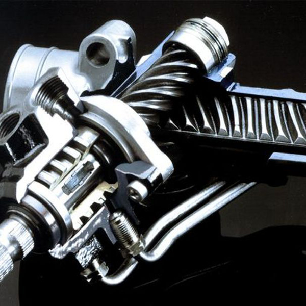
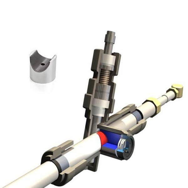
A. Rack and pinion steering structure analysis
The rack-and-pinion steering gear is mainly used to achieve the steering function by driving the tangential motion of the rack through the rotation of gears. The steering gear is arranged at the lower end of the steering drive shaft and meshes with the rotating rack. When the driver turns the steering wheel, the external torque is transmitted by the steering column and universal joint, which drives the pinion in the steering gear to make a rotary motion, and then drives the rack in the steering gear to convert the motion into a linear motion tangentially along with the steering wheel. The gears then drive the rack in the steering gear to convert the motion into a linear motion tangential to the steering wheel.

B. Steering System Parameter Determination
Before the steering system can be designed and manufactured, and before the parts can be modeled and assembled, the parameters of the parts and assemblies need to be determined, and then these parameters can be used to model and assemble the parts in CATIA.
The steering system parameters are mainly obtained from two sources. On the one hand, a large amount of data such as race rules, race track, and driver’s actual condition should be collected initially and then calculated by substituting the collected data into the formula. The main parameters include the maximum steering angle, steering gear ratio, steering column geometry height, etc.
On the other hand, the data from previous years’ racing cars are compared with the actual situation and obtained by using empirical formulas, such as gear modulus, number of teeth, pressure angle, rack stroke, etc. The main modeling parameters are shown in Table 1.
Table 1 Main modeling parameters
| Parameters | Value |
|---|---|
| Maximum steering angle/° | 27 |
| Modulus/mm | 1.5 |
| Number of teeth | 17 |
| Pressure angle/° | 20 |
| Total rack travel/mm | 60 |
| Geometric height of steering column/mm | 90 |
2) CATIA Modeling
CATIA is CAD software that integrates design, modeling, and analysis aspects. CATIA shows its powerful modeling capabilities for a large number of complex shapes in the automotive industry.
In the steering system modeling, a sketch of the steering column geometry and trapezoidal geometry is first drawn based on the modeling parameters, which is used as the basis for the part design.
After the part design is completed, the parts are gradually imported into CATIA assembly design for assembly operations.
CATIA assembly design is performed by adding fits and constraints between parts. Common constraints include coaxial, contact, offset, etc. After successful completion of the assembly operation, the assembly shown in Figure 2 can be obtained.
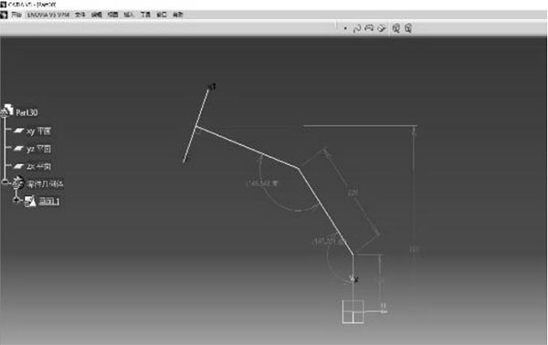
Fig. 1 Geometric sketch of the steering column
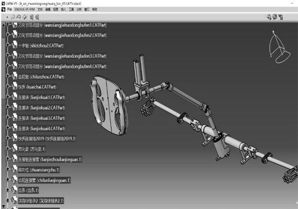
Fig. 2 General assembly of the steering system
2 Finite element analysis of the part
After the initial modeling of the part is completed, the strength of the part needs to be verified. The finite element analysis of the part is used to obtain the perfect size of the part and to complete the material selection of the part. This will prevent some parts from breaking during the actual operation of the car due to weakness; on the other hand, it will prevent some parts from increasing the mass of the car due to excessive material, even though they are not subject to much force.
ANSYS has powerful kinematic and dynamics solvers that can effectively analyze the mechanical properties of structures such as stresses and strains. ANSYS' static structural analysis and modal analysis modules are used to perform finite element analysis of the steering system components and complete the component verification.
1) Determination of steering system loads
Before ANSYS can be used for analysis, the load parameters of each component need to be obtained.
These forces are influenced by external factors such as the vertical load on the steering wheel, the friction coefficient of the road surface, and the type of tire, as well as by design factors such as the steering gear ratio and the pressure angle between the tie rods of the steering system. Although it is difficult to calculate these forces accurately, the FSAE track material is asphalt, so semi-empirical formulas are available for asphalt pavements with sufficient accuracy. Table 2 shows the data obtained using these formulas and the parameters measured for the race car.
Table 2 Calculated load parameters
| Parameter | Value |
|---|---|
| n-place steering torque/N*mm | 36 080 |
| Steering output force/N | 62.88 |
| Steering hand force/N | 646 |
| Racing full mass/kg | 308 |
| Steering wheel diameter/mm | 270 |
2) Finite element analysis
A. Overview of the principle of finite element analysis
The basic idea of the finite element method is to discretize the continuous solution area into a finite set of units that are interconnected in a certain way. According to the actual situation of the structure, choose the appropriate cell shape, type, number, size, and arrangement, and hypothetically divide the object to be analyzed into a finite collection of partitions or blocks. By introducing forced boundary conditions, the equations are solved to obtain the relevant nodal displacements.
B. Part analysis
Before the finite element analysis of the parts, the force analysis of each part is carried out by using the calculated load derived above to obtain the main stresses on the parts and the way of stresses during the steering process, including the contact stress between the rack and pinion, the thrust on the fixed end of the rack housing, the torque on the steering column, and the thrust on the tie rod. The following is a discussion of the rack and pinion as an example.
When using ANSYS for the finite element analysis of the gear and rack, in order to obtain more accurate gear contact stresses and achieve contact finite element meshing, a more accurate meshing can be obtained by using local cell sizes. To determine the boundary conditions of the tooth contact, the gear and rack are constrained so that the gear has only the freedom of rotation around its central axis of rotation and the rack has only the freedom of movement along its axis of motion. Select the central cylindrical surface of the gear and apply the torque of rotation around its center of rotation. Solve for the target and view the simulation results. The contact stress cloud of the gear is shown in Figure 3.

Fig. 3 Gear rack contact stress analysis
3 Steering System Dynamics Simulation
1) Introduction of ADAMS/CAR modeling process
There are two working environments in ADAMS/CAR software, one is "Template Builder", which is the module building environment, and the other is "Standard", which is the standard environment. Each environment has a different interface and menu. The user builds the modules for each subsystem in the Template Builder environment, which specifies the topological relationships between the components and then modifies the template parameters under the standard module to form a specific, customized subsystem.
Then, initial hard points and dynamics parameters are entered. The hard points are the key geometric positioning points for the connection of the parts. In steering systems, the location of the disconnect point is the key hard point that affects the Ackermann percentages. The initial location is often determined using the three-center theorem and then adjusted based on post-simulation results. Dynamic parameters, including part mass, the center of mass position, and rotational inertia, can be measured and calculated based on actual race car data.
Finally, simulations and results are analyzed.
2) Example Analysis
The dynamics simulation of the FSAE racing car steering system is focused on wheel runout analysis and rotation analysis.
During the driving process of the car, the tires will jump up and down, resulting in changes in the positioning parameters and tire parameters. The runout analysis provides information about the changes in the parameters and also determines whether the cross-ties are strong enough and whether they interfere with the A-arms of the suspension. The rotation test can determine whether the tie rod interferes with the hub, and the simulation results can be used to determine the Ackermann percentage.
First, enter the working environment, open the corresponding module or import the established 3D model to obtain the steering and suspension system template. The prepared hard point coordinates and dynamics parameters are entered into the model. Based on the generated assembly model, a preliminary judgment is made as to whether the length and position of the parts are reasonable and whether they will interfere with the suspension.
A. Wheel hopping experiment
After presetting the parameters such as the range of up and down jumps and the number of jumps, click Run. After finishing, enter the post-processing module and check the corresponding parameter changes during wheel hopping as needed, and then analyze the curve to optimize each parameter. The simulation of wheel hopping is shown in Figure 4.

Fig. 4 Wheel hop simulation
B. Rotation Experiment
For the rotation experiment, similar to the wheel hopping experiment, the simulation is performed by entering the initial values in the corresponding module. At the end of the simulation run, the relevant data curves are obtained. The results of the rotation simulation are shown in Figure 5.
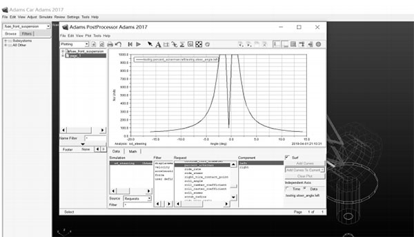
Fig. 5 Rotation simulation results
The Ackermann percentage is one of the important parameters of the steering system, and to obtain the ideal Ackermann percentage, the hard point parameters need to be adjusted continuously.
The sensitivity analysis is often performed in the rotation experiment to obtain the degree of influence and effect of the relevant hard point on the target value so that the hard point parameters can be adjusted easily. The percentage the degree of influence of each hard point value on the Ackermann percentage is shown in Figure 6
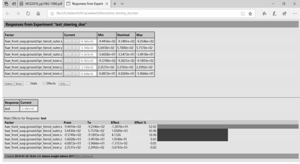
Fig. 6 Percentage effect of each hardpoint value on Ackermann percentage
The sensitivity analysis shows that the x and y values of the outer point and the x value of the inner point have the greatest effect on the Ackermann percentage, while the other values have little effect. Therefore, in the adjustment process, the ideal Ackermann percentage is obtained by adjusting the values of the inner and outer points.
4 Conclusion
In this paper, CAD/CAE technology was used to model and simulate the steering system of the FASE race car in three dimensions. The application of CAD/CAE technology has also greatly reduced the design cost, shortened the design cycle, and improved the accuracy of the design parameters, which has played a significant role in the design and manufacturing process of the Formula One race car.
Reference
[1] Study on the application of CAE technology in automotive design [J]. Wang Guofeng. Times Automotive. 2020(10)
[2]CAD/CAE simulation design of the rack and pinion steering gear[J]. Hu Jiawei, Yang Hu. Automotive Practical Technology. 2019(06)
[3] Modeling and analysis of rack and pinion steering [J]. Liu Bing. Journal of Shanghai University of Engineering and Technology. 2006(01)
(We do not share your data with anybody, and only use it for its intended purpose)
The Previous Articles:
What Is Rack and Pinion Bushing? How To Tell If Rack and Pinion Bushings Are Bad?
Why Steering Rack Makes Noise When Turning?
How To Rebuild A Steering Rack?
What Is A Rotary Valve Power Steering Rack?
Rack And Pinion System Vs Power Steering System: What Are The Differences?
Power Steering Rack Market Analysis Report (Japan Market)
What Causes Steering Rack to Go Bad?
Design Of Car Rack And Pinion Steering Racks
What Is The Intelligent Steering Rack Used By VW, Toyota, Honda And Renault?


Leave A Comment