With the continuous development of the automotive industry, front-wheel drive and lightweight steering have become the development trend in the automotive industry. The rack and pinion transmission mechanisms can greatly meet the design requirements of a lightweight car steering mechanism. Through continuous improvement of rack and pinion transmission structure, breakthroughs in key technologies such as transmission mechanism inverse transmission efficiency and transmission mechanism variable transmission ratio make rack and pinion transmission mechanism widely used in light cars and buses.
The main structure of the rack and pinion steering rack is composed of gears, rack, housing, and other components. Compared with other steering gears, rack and pinion gearboxes have the advantages of lightweight structure, fewer overall parts, high transmission efficiency, and low manufacturing cost; meanwhile, the spring connection reduces the gap between the steering gear and the steering rack, improves the strength and stiffness of the steering connection parts and enhances the steering stability of the vehicle.
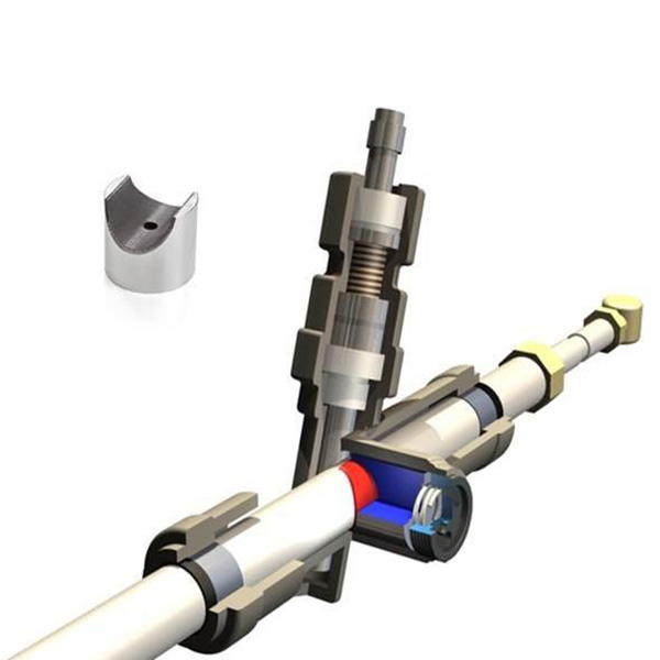
1 Rack and pinion steering rack
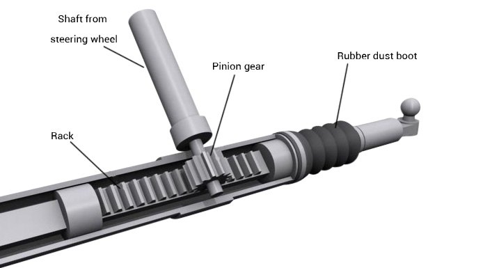
1)Steering gear structure and principle
At present, the rack and pinion steering structure generally adopt the side input and middle output scheme; the bar is fixed near the rack and the end extends to the center of mass of the car; through the tie rod swinging from side to side, the steering shaft does the head swing and then realizes the rotation. Some research shows that: with the increasing length of the tie rod, the wheel will reduce the swing of the tie rod swing angle during the up and down swing of the suspension, thus reducing the possible mutual interference between the steering mechanism and the suspension system during the steering or downward driving of the car.
Another commonly used structure is the output at both ends, and the length of the steering tie rod is limited to a certain range. Studies have shown that shorter tie rod lengths are likely to cause interference with the guiding mechanism of the suspension system. structure to produce motion interference.
2) Steering rack
Steering rack is mainly designed for rack end face, currently, There are mainly round section rack, V section rack, and Y and round section rack, the common ones are The advantage of V- or Y-shaped end face is that it consumes The advantages are that the material consumed is less, about 20% less, and the mass is smaller. The two bevels located under the teeth are in contact with the rack brackets. The two beveled surfaces under the teeth can be used to prevent the rack from rotating around the axis when they are in contact with each other. If the tooth width of the Y-shaped cross-sectional rack can be made wider, it can effectively prevent the rack from rotating around the axis. If the tooth width of the Y-shaped cross-sectional rack could be made wider, it would effectively increase the strength. A gasket made of an alkaline material (e.g. PTFE) is usually installed on the rack. is usually installed between the rack and the carrier to reduce (Figure 1).
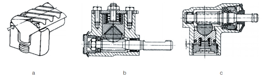
Fig. 1 Shape of the rack section of the steering gear
2 Design of gears
1) Selection of gear parameters
Grade 7 accuracy is selected
Table 1 Dimensional design parameters of gears
| Number | Item | Symbol | Dimensional parameters (mm) |
|---|---|---|---|
| 1 | Overall length | L | 198 |
| 2 | Tooth width | B1 | 60 |
| 3 | Number of teeth | Z1 | 7 |
| 4 | Normal modulus | Mn1 | 3 |
| 5 | Helix angle | n | 14° |
| 6 | Helix direction | Left rotation |
Gear material selection.
Pinion gear: 16MnCr5 Carburized and quenched Tooth surface Hardness 56-62 HRC
Large gear: 45 steel surface quenching Tooth surface hardness 50-56HRC
2) Gear tooth root bending stress calibration
In this paper, the gear materials shown in Table 1 are used, and the material characteristics are substituted into the corresponding calculation equation, and the helix angle coefficient Yβ is introduced because the contact line inclination will have a corresponding effect on the bending strength.
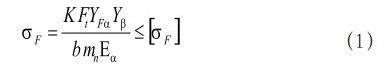
It can be obtained, [σF]=1.5*1000/1.5=1000MPa, so σ F < [σF]
In summary, the gear meets the strength requirements of the design.
3) Calculation of the degree of tooth contact fatigue
Working load of the gear
The average load P (in N/mm) per unit length along the tooth contact line is
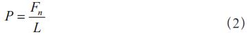
Fn - the normal load acting on the contact line of the tooth surface
L - the length of the contact line along the tooth surface in mm
The maximum load per unit length of the contact line is
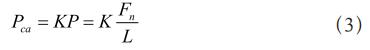
K - load factor
The load factor K includes the use factor KA, the dynamic load coefficient KV, the inter-tooth load distribution coefficient Kα and the toothwise load distribution coefficient Kα. number KV, the inter-tooth load distribution factor Kα and the tooth direction load distribution factor Kβ. distribution coefficient Kβ , i.e.
K = KAKV KαKβ
The service factor KA is a factor that takes into account the effect of additional dynamic loads caused by external collars during gear meshing. is the coefficient that takes into account the effect of the additional dynamic load caused by the external lead device during gear meshing.
KA = 1.0
The dynamic load factor KV , because gear manufacturing and assembly errors are inevitable and the gears are subjected to elastic deformation after being loaded. The dynamic load factor is therefore introduced.
KV =1.0
Inter-tooth load factor Kα
Manufacturing accuracy of gears Class 7 accuracy
![]()
/mm
3 Design of the rack
1) Selection of rack parameters
Table 2 Parameters of the rack
| Number | Item | Symbol | Dimensional parameters (mm) |
|---|---|---|---|
| 1 | Overall length | L | 767 |
| 2 | Diameter | D | 30 |
| 3 | Number of teeth | Z | 20 |
| 4 | Normal modulus | Mn2 | 3 |
Material selection
45 Steel Tempered 229-286HBS
2) Checking the positive stress of the rack rod
The tensile stresses in the rack rod section are
![]()
F - the axial force on the rack
A - cross-sectional area of the rack root, A=562mm²
The tensile strength limit is σ b = 690N / mm², (without considering the effect of heat treatment on the strength).
Therefore, σ < σ b , so the rack design meets the tensile strength design requirements.
3)Calibration of the bending stress in the teeth of the rack
Single tooth bending stress.
![]()
In the formula: - rack tooth tangential force
b - dangerous section at the tooth length along the tooth width
h1 - rack calculated tooth height
S -- dangerous section tooth thickness
From the above conditions, the bending stress of the rack teeth can be calculated as follows
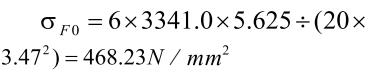
Tooth bending safety factor.
![]()
4 Selection and calculation of components
1)Selection of gear bearing
Check the 《Mechanical Engineering and Automation Design Manual》
Select NA4901 needle roller bearing, inner diameter 12mm, outer diameter 26mm, width 13mm, basic rated dynamic load Cr=96kN, basic rated static load Cor=108kN, the limit speed is about 190,000r/min.
Select 6204 deep groove ball bearing with 20mm inner diameter, 47mm outer diameter, and 14mm height. Outer diameter 47mm, height 14mm, basic dynamic load rating Cr=158KN, static load Cor=7.88KN. The ultimate speed is about 2000r/min.
Option 6204 deep groove ball bearing, 20mm ID, 14mm height Outer diameter 47mm, height 14mm, basic dynamic load rating Cr=158KN, static load Cor=7.88KN. The limit speed is about 2000r/min.
2) Design and calibration of gear shaft
In this paper, the material of gear shaft is also chosen to be made of 20MnCr5 and quenched by carburizing. The corresponding characteristic parameters are: 20MnCr5, hardness of 60HRC, tensile strength limit [σB] = 1100MPa, yield limit [σs] = 850MPa, bending fatigue limit [σ-1] = 525MPa, shear fatigue limit [t-1] = 300MPa, speed n = 10r/min.
According to the formula
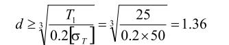
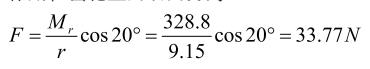
The resistance moment acting on the rack and pinion is Mr=328.8N*m, and the axial force acting on
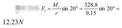
The tangential force acting on the gear is
Therefore, an integral gear shaft design is used

5 Conclusion
This paper selects the helical cylindrical gear and rack meshing method as the specific object of this paper. The specific research object of this paper, through the study of gear and rack and the accurate design and calculation of each component to The research is to meet the requirements of the strength of the steering gear and the correct transmission ratio. In order to achieve the stability and responsiveness of vehicle steering
The Previous Articles:
What Is Rack and Pinion Bushing? How To Tell If Rack and Pinion Bushings Are Bad?
Why Steering Rack Makes Noise When Turning?
How To Rebuild A Steering Rack?
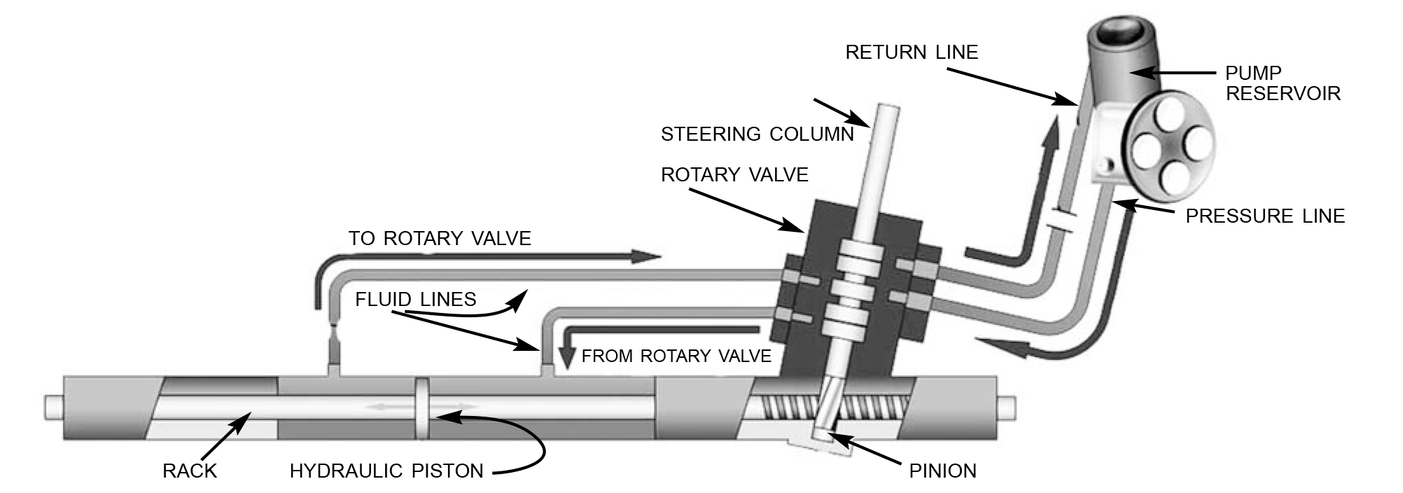
What Is A Rotary Valve Power Steering Rack?
Rack And Pinion System Vs Power Steering System: What Are The Differences?
Power Steering Rack Market Analysis Report (Japan Market)
What Causes Steering Rack to Go Bad?
Design Of Car Rack And Pinion Steering Racks
What Is The Intelligent Steering Rack Used By VW, Toyota, Honda And Renault?


You made a number of fine points there. I did a search on the topic and found the majority of people will consent with your blog.
I regard something genuinely special in this website .
I conceive you have mentioned some very interesting details, regards for the post.