The power steering rack, in essence, is based on mechanical steering. With the addition of the power steering rack transmission, the driver's steering effort is much reduced. The driver's burden is light, requiring only a small amount of force to complete the steering, with the bulk of the steering being provided by the engine-driven oil pump.
This paper describes the construction of the power steering mechanism of the Model ZF8098 power steering rack and illustrates its operation by means of hydraulic fluid flow.
1. Structure
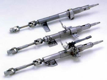
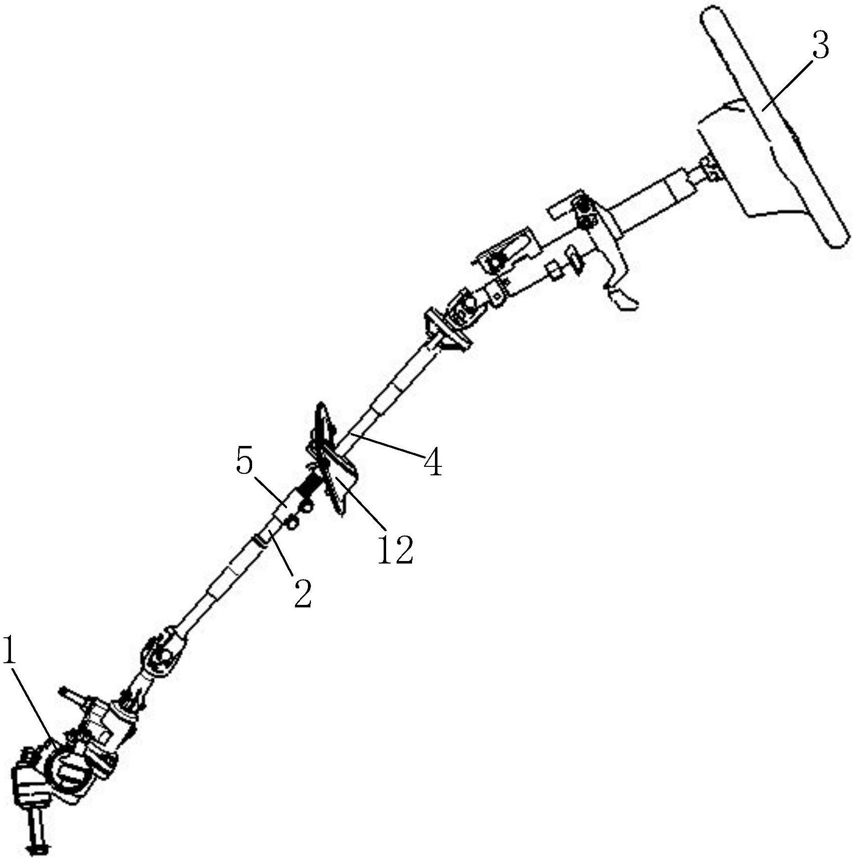
Figure 1 shows the ZF8098 series power steering gear. The first part is the mechanical steering gear, the second part is the power cylinder, and the third part is the distribution valve. The oil tank stores the oil required for the system to work. The oil is supplied to the power steering rack by the steering pump driven by the engine, and the oil enters the steering gear from the tank. The pressure oil from the steering gear flows back to the tank, and the oil continues to circulate.
The moving energy of the power cylinder comes from the energy generated by the difference in oil pressure between the two end chambers. The power cylinder consists of a housing and a piston. The inner part of the piston and the outer part of the screw has a spiral groove with an approximate semicircular cross-section, and the two form a tubular channel with many steel balls. Usually, the steering shaft and the spool are made into one part, while the screw and the sleeve are made into one part. During the rotation of the steering shaft, the balls roll in a circular manner on the passage, which completes the transition from the rotary motion of the screw to the linear motion of the piston, and also drives the rocker arm fan shaft to rotate. This process completes the conversion from the rotary motion of the screw to the linear motion of the piston and also drives the rocker gear fan shaft to rotate. The torsion bar is held in place by a pin and is connected to the rotary valve. The safety valve is used to reduce the oil pressure in the steering gear to prevent damage to the steering gear from excessive oil pressure. The function of the oil filling valve is to reduce the oil pressure in the steering gear when the steering pump is not working. The purpose of the fill valve is to replenish the steering gear in a timely manner when the steering pump is not in operation. The valve is a key component. The relative rotation between the valve sleeve and the spool directly determines the fluid flow and the amount of boost.
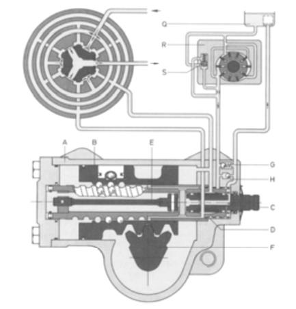
Figure 1 ZF8098 power steering gear
A-Housing B-Piston C-Shaft-Spool D-Screw-Sleeve E-Torsional rod F-Rocker tooth fan shaft G-Safety valve H H - oil filling valve Q - oil tank R - steering pump S - constant flow valve
2. Principle of assistance
1) Straight-line driving conditions
When the car is running in a straight line, i.e., when the steering wheel is not moving, the torsion bar does not rotate and the distribution valve is in the middle position. Figure 2 illustrates the flow of pressure oil through the power steering transmission. Normally, there is an oil passage in the steering housing through which the oil enters the valve sleeve with an open hole during normal operation. The distribution valve is composed of a sleeve and a rotary valve with six grooves inside the sleeve and six grooves on the exterior of the spool. The grooves of the sleeve and the grooves of the spool are staggered and correspond to each other, and the oil reaches the piston through the gap between the grooves. Since the distribution valve is in the middle position when the car is driving in a straight line, the oil flows to the left and right chambers of the piston and finally flows back to the oil tank through the return groove on the spool.
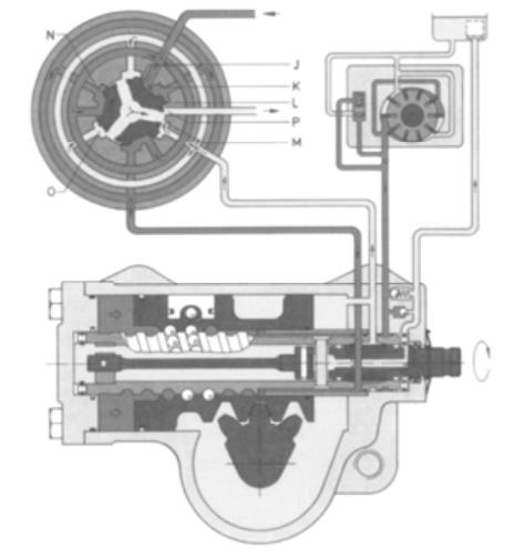
Figure 2 Oil flow direction
J - oil inlet slit K - oil inlet slit L - oil return slit M - oil return slit N - axial slot O - axial slot P - oil return slot
2) Steering driving conditions
When the car turns right, the steering wheel needs to turn right, which makes the steering shaft (spool) transfer torque to the screw (sleeve) through the action of the torsion bar, and the sleeve deviates from the initial middle position. At this point the sleeve and spool move relative to each other and the spool turns right relative to the sleeve, resulting in an angular displacement as shown in Figure 3. This angular displacement closes the gap between the right side of the six spool shoulders and the sleeve groove while increasing the gap between the left side of the six spool shoulders and the sleeve groove, through which the oil flows. As a result, the pressure oil flows into the axial groove on the sleeve and then through the tubular channel into the left chamber of the piston. When the amount of pressure oil in the left chamber is gradually increased, the pressure oil in the right chamber enters the oil tank by using the return slit and the return groove as a channel. During the whole process, a certain pressure difference is generated in the left and right chambers of the power cylinder, which also makes the piston move to the right and the hydraulic power steering is realized.
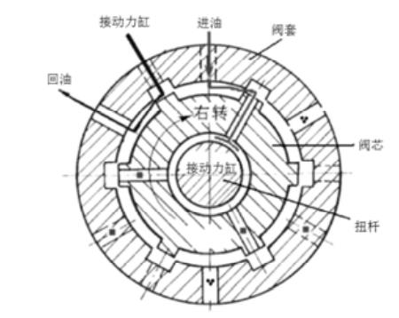
Figure 3 Variation of distribution valve during right steering
As the car turns left, the spool turns left with respect to the sleeve, resulting in an angular displacement, as shown in Figure 4. This angular displacement causes the gap between the left side of the 6 spool shoulders and the gap between the left side of the 6 spool shoulders and the groove of the sleeve to be closed, and the gap between the right side of the corresponding 6 spool shoulders and the groove of the sleeve is increased. The gap between the right side of the corresponding 6 spool shoulders and the sleeve groove increases, i.e. the oil inlet slit increases and oil flows through. As a result, the pressure oil flows into the axial groove on the valve sleeve and then enters the right chamber of the piston through a tubular channel. At this point, the pressure oil in the right chamber of the power cylinder increases, and the pressure oil in the left chamber of the piston returns to the tank through the return slit and return groove. This process makes hydraulic power steering possible.

Figure 4 Variation of the distribution valve during left steering
A torsion bar is a component with good rotational elasticity. When the torsion bar deforms, due to the interaction of forces transmitted to the steering wheel reaction, the driver can feel the change in force, the so-called "road sense". The car in In the process of operation, if the car is always steering in one direction, the steering wheel will keep a certain angle unchanged, and the torsion bar will also keep the corresponding state, so the valve spool and valve sleeve keep a fixed opening degree, and the torque generated by the power cylinder fluid difference and the return torque balance, so the wheel rotation angle will be maintained.
3) Steering return performance
When the driver's control of the steering wheel changes, the position of the distribution valve returns to the middle state due to the elasticity of the torsion bar, which closes the gap between the sleeve and the spool of the distribution valve. However, after taking into account the backward tilt of the main pin and the inward tilt of the main pin, the return torque generated will ensure that the wheels will return to the right position without requiring the driver to perform corresponding operations.
4) Steering follow action
During the form of the car, the torsion speed of the torsion bar is related to the rotation speed of the steering wheel, and the steering wheel rotates faster, which also drives a series of components to operate. The accelerated rotation of the steering wheel also drives a series of components to move. The first is the increase of the angular displacement of the valve sleeve and spool, and then the oil pressure difference in the power cylinder gradually increases, causing the steering wheel deflection speed to accelerate gradually. This shows that the steering wheel turns, the front wheel turns, and the steering wheel turns faster, the front wheel also turns faster. When the steering force is lost, the torsion bar returns to the free initial state, the distribution valve returns to the initial state, and the power cylinder stops working. This power When the steering force is lost, the torsion bar returns to the free initial state, the distribution valve returns to the initial state, and the power cylinder stops working. This is called the follower action of the steering gear.
3. Limiting protection function
A restrictor is usually installed on the power steering to reduce the pressure and drainage to prevent damage to the steering gear and steering pump under high operating pressure. Figure 5 shows a double-acting restrictor, which consists of two spring-loaded spools at the ends of the power cylinder piston.
As the power cylinder piston moves to the right, the right spool gradually moves closer to the right adjusting screw. When the range of movement reaches its limit, the right spool is pushed into the piston, causing the pressure in the left chamber to increase, which in turn causes the left spool to be pushed into the piston. The opposite is true when the power cylinder piston moves to the left to the limit position. When the limiter is in working condition, the steering can still swing, but because the pressure difference between the two chambers of the power cylinder decreases, the hydraulic booster effect is greatly reduced, and at the same time, the steering force increases until the limit position.
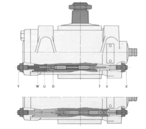
Figure 5 Hydraulic steering limiter
T - right spool U - left spool V - right piston chamber W - left piston chamber X - right adjusting screw Y - left adjusting screw
4. Power Assist Failure
The driver can still steer the car through the mechanical part of the steering gear, but the hydraulic power steering device has failed, so the driver feels a heavy feeling when steering.
5. Conclusion
In this paper, the structure of the rotary valve power steering has been introduced systematically and the power steering principle has been described in detail. The most important features of this steering gear are its high sensitivity, relatively small number of seals, and short axial dimensions. Although technology is developing more and more rapidly, there are Although technology is developing rapidly and new advanced steering technologies such as steer-by-wire (SBW) and four-wheel steering (4WS) have emerged, but they still have many shortcomings in terms of reliability and application technology. The mainstream application is still the rotary valve power steering, which still has a good application prospect.
References
[1]Discussion on the development trend of automotive steering assembly[J]. Zhang Yufei,Li Hong,Yu Jinlong. Auto Parts. 2012(12)
[2]Inspection and adjustment of the steering system and troubleshooting of Steyr truck [J]. Lu Tao. Auto repair. 2008(02)
The Previous Articles:
What Is Rack and Pinion Bushing? How To Tell If Rack and Pinion Bushings Are Bad?
Why Steering Rack Makes Noise When Turning?
How To Rebuild A Steering Rack?
What Is A Rotary Valve Power Steering Rack?
Rack And Pinion System Vs Power Steering System: What Are The Differences?
Power Steering Rack Market Analysis Report (Japan Market)
What Causes Steering Rack to Go Bad?
Design Of Car Rack And Pinion Steering Racks
What Is The Intelligent Steering Rack Used By VW, Toyota, Honda And Renault?
You made some good points there. I looked on the internet for the issue and found most guys will consent with your website.
I was very pleased to find this web-site.I wanted to thanks for your time for this wonderful read!! I definitely enjoying every little bit of it and I have you bookmarked to check out new stuff you blog post.