When I first started at Steeringly, I didn't know anything about the steering rack! I was baffled by all the different kinds of steering gears!
So I collected a lot of information and read a lot of literature and videos to understand the steering rack. I surfed the internet recently and found that many people were just as confused as I was at that time, facing so many types of steering gears! So I organized the information I read before, and I hope my article will be helpful to you!
Check out the table of contents below to get directly to the places you're most interested in!
1 Mechanical steering rack
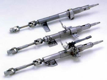
The mechanical steering rack is a purely mechanical structure, which is driven only by human power during the steering maneuvering process, without external force. The most widely used ones are rack and pinion steering rack, recirculating ball steering rack, and worm gear crank finger pin steering rack.
1) Rack and pinion steering rack
a. What is a rack and pinion steering rack?
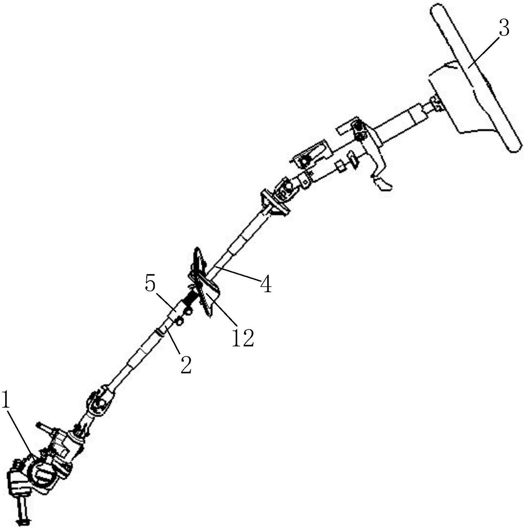
The rack and pinion steering gear is the simplest structure and the easiest to produce. The rack and pinion steering gear mainly consist of gears, rack, adjusting screw, steering housing, and rack guide block. There is a spring between the adjusting screw and the rack, which is rotated to give the rack a force in the direction of the gear, thus making the two join closely, and the rack guide is related to the movement of the rack. The steering gear is at the lower end of the steering shaft and engages with the steering rack in the steering housing. When the driver manipulates the steering wheel, the gear is rotated by the steering shaft, and the meshing of the rack and pinion drives the movement of the rack in the steering gear in the horizontal direction, while the end of the steering gear rack is connected to the end of the steering tie rod, thus transferring the force to the steering knuckle arm and driving the wheel deflection to achieve steering.

b. Advantages and disadvantages of rack and pinion steering gears
- Advantages: compact and simple structure, low manufacturing cost, its transmission efficiency can reach 90%, and if there is a gap between the gear and rack due to wear, the adjustment screw and spring installed in the steering housing, located at the back of the rack to apply pressure, can eliminate the gap between the teeth, and because there is no steering rocker and straight tie rod, so the steering wheel turning angle can be increased.
- Disadvantage: the backlash efficiency is too high, up to 60%-70% when the car driving road is uneven, most of the impact between the steering wheel and the road can be retransmitted to the steering wheel, this phenomenon is called backlash, the backlash phenomenon will make the driver difficult to accurately control the driving direction of the car, and will cause injury to the driver due to the "hand" phenomenon. This phenomenon is called backlash.
To sum up, large cars almost do not use a pure mechanical rack and pinion steering, more with the power steering device, small cars field more rack and pinion steering, such as civilian cars, beach cars, etc.
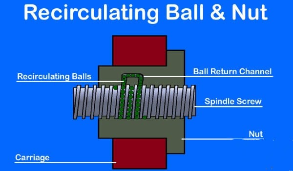
2) Recirculating ball steering rack
a. What is circulating ball steering gear?
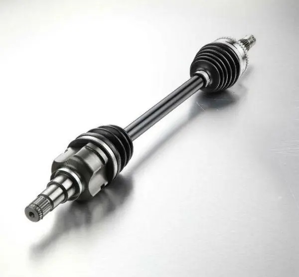
The main components of the recirculating ball steering gear consist of the nut, screw, steering housing and many small steel balls, the recirculating ball in the recirculating ball steering refers to these small steel balls, the small steel balls are placed in the closed pipe between the nut and the screw, fixing the steering column and the screw together, when the screw turns, the screw can push the nut to move up and down, and then the nut drives the steering gear by pushing the gear to achieve the purpose of steering. When the screw is turned, the screw can push the nut to move up and down, and then the nut can push the gear to drive the reciprocating motion of the rocker's arm to achieve the purpose of steering. In this regard, the recirculating ball steering has two stages of transmission, the steering screw, and the steering nut constitute the first stage of transmission, and the steering screw is connected with the steering shaft; the rack and the geared fan constitute the other stage of transmission, and the rack is machined on the lower plane of the steering nut, and the geared fan is integrated with the gear fan shaft. Therefore, the steering nut is not only the follower of the first-stage transmission but also the active member of the second-stage transmission. As the steering screw and the steering nut slide relative to each other, in order to reduce the friction and wear between them, the threads of the two are made into a raceway, and the middle of the raceway is equipped with many steel balls, thus transforming the sliding friction into rolling friction. The steering nut is equipped with two steel ball conduits filled with steel balls, which are connected to the raceway, forming two independent closed channels for the steel balls to circulate and roll. In this steering process, the small steel balls are always cyclically rolling in the closed pipeline, so this type of steering gear is called cyclic ball steering gear.
b. Advantages and disadvantages of recirculating ball steering gear
- Advantages: Compared with rack and pinion steering, the recirculating ball steering relies more on rolling friction, so the transmission efficiency is higher, the auto-return effect is better, the operation is lighter and more comfortable, and the wear of all mechanical parts is smaller, so the service life is relatively long.
- Disadvantages: Because of the relatively complex structure, it is not easy to install the steering power device, and because of the two-stage transmission, it is not strong when using the circulating ball steering. The manufacturing process is relatively complicated. The reverse transmission efficiency is high, and the road impact is easily back-driven to the steering wheel, resulting in a "hitting" situation, and the steering wheel shaking and oscillation phenomenon is easy to occur.
As mentioned above, the circulating ball steering gear is mostly used in medium and large commercial vehicles, and with the gradual updating and improvement of the steering power system, its use in small cars is gradually decreasing.
3) Worm gear crank finger pin type steering gear
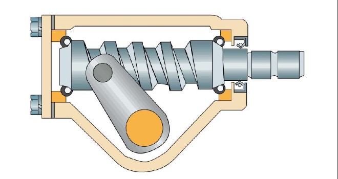
a. What is worm gear crank finger pin type steering gear?
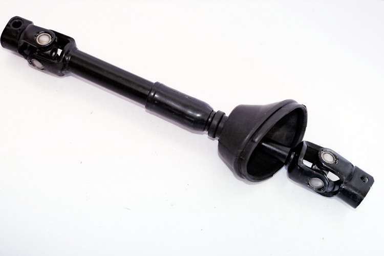
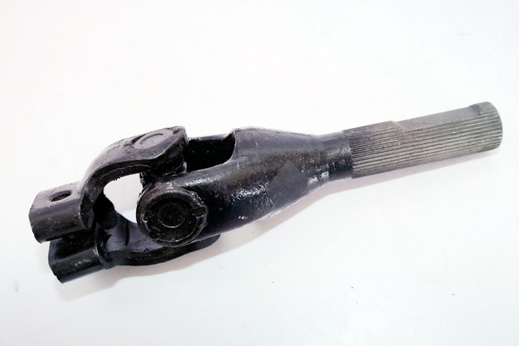
The worm gear crank finger pin type steering gear mainly consists of a steering worm, steering rocker crank, finger pin, side cover and steering gear housing, etc. The steering gear housing is fixed on the steering gear bracket of the car frame, and the transmission sub is installed in the housing, in which the steering worm is the active part and has trapezoidal section threads, which are supported on the two ball bearings at both ends of the steering gear housing, and the finger pin installed at the end of the rocker crank is the follower. When the car is steered, the driver drives the steering worm through the steering wheel, which makes the finger pin engage with it to rotate itself and make a circular motion around the axis of the rocker arm shaft in the thread groove of the worm with the crank as the radius, so as to drive the crank and then drive the swing of the steering rocker arm to achieve the purpose of steering the car.
b. Advantages and disadvantages of worm gear crank finger pin steering
- Advantages: The finger pin steering works under the condition of complete rolling friction, so it has high transmission efficiency and light handling, and it is easy to arrange and maintain the whole car and improve the safety of driving because of the segmented steering shaft. The reversing transmission efficiency is low, the road impact force to the steering wheel is small, good stability, simple manufacturing, easy maintenance
- Disadvantages: the volume occupies a large, inconvenient layout.
In summary, the worm gear crank finger pin type steering gear is mostly used for large vehicles that require large steering force.
2 Power steering rack(power steering system)
A power steering rack is actually a combination of mechanical steering gear and steering power unit to form. At present, the most widely used are hydraulic power steering systems (mechanical hydraulic power steering gear and electric hydraulic power steering rack) and electric power steering systems.
1) Hydraulic power steering system
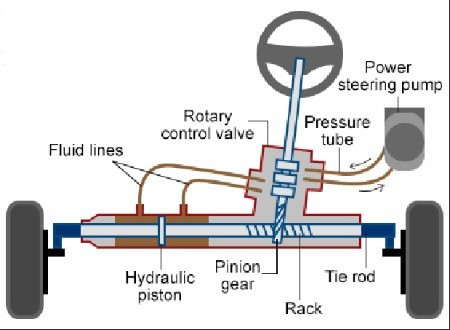
a. What is the hydraulic power steering system?
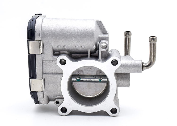
The main components of the mechanical hydraulic power steering system are the hydraulic pump, oil pipe, V-drive belt, pressure fluid control valve, and oil storage tank. The engine is the power source of the hydraulic power steering system, and the steering oil pump is driven by the engine. The steering control valve provides steering power by controlling the direction of oil flow and the size of oil pressure, thus reducing the driver's force on the steering wheel and achieving the power-assist effect. On top of the mechanical hydraulic power steering system, there is also an electro-hydraulic power steering system, whose structure increases the hydraulic reaction device and fluid flow distribution valve, and the additional electronic control system, which includes a speed sensor, power steering ECU, solenoid valve, etc. An electronically controlled hydraulic power steering system uses electronic control unit to regulate the role and adjust the power on the steering wheel according to the vehicle speed, while changing the size of the auxiliary force of the hydraulic power system is by controlling the degree of opening of the steering control valve, so as to achieve different speeds to adjust the power characteristics of different auxiliary steering force.
b. Advantages and disadvantages of the hydraulic power steering system
For the mechanical hydraulic power steering system, although it has good power performance and handling stability at low and medium speeds, the fixed power effect will make the steering wheel too sensitive and make the driver's road sense worse when driving at high speed, and because the engine will always drive the oil pump to rotate during the vehicle driving process, thus causing the waste of engine energy. For the electro-hydraulic power steering system, the size of the power will be different when driving at high and low speeds, and at low speeds, the system power is large, and the driver will be more light and flexible; at high speeds, the power is weakened, so that the driver's maneuvering force increases, compared to the hydraulic power system will have a clear sense of the road, not only to ensure the flexibility of steering maneuvering but also to improve the stability of steering at high speeds and a sense of security. However, the electro-hydraulic system is complicated and expensive, and the disadvantages of the hydraulic power steering system, such as low efficiency and high energy consumption, have not yet been overcome.
2) What is the electric power steering system?
The electric power steering system is mainly composed of the electronic control unit (ECU), torque, and the same. The expected data on the failure rate of electronic components such as semiconductor discrete devices, optocouplers, microelectronic components, relays, electrical connectors, power filters, crystals, power converters, printed circuit boards, and solder joints in the hydraulic manipulator controller can be obtained from the relevant data of GJB299C, and the specific expected data is shown in Table 1. Table 1 shows the expected data
Table1 Estimated failure rate of electronic components in underwater hydraulic manipulator controller
| Serial number | Component type | λp/(10-6/h) |
|---|---|---|
| 1 | Resistance | 0.638 4 |
| 2 | Capacitor | 0.338 34 |
| 3 | Semiconductor Discrete Devices | 0.721 44 |
| 4 | Photocouplers | 0.729 945 |
| 5 | Microelectronic Components | 1.007 67 |
| 6 | Relays | 0.290 3 |
| 7 | Electrical Connectors | 1.161 81 |
| 8 | Power filter | 2.08 |
| 9 | Crystal oscillator | 1.925 |
| 10 | Power converter | 2.775 |
| 11 | Printed Circuit Boards | 0.219 15 |
| 12 | Weld joints | 0.356 46 |
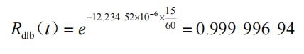
| Total | --- | 12.243 52 |
Since the lifetime of electronic products obeys an exponential distribution, R(t) = e-λt , it is possible to calculate the task reliability of the hydraulic manipulator task profile within 15 min as
4 Conclusion
This paper illustrates the application of the reliability prediction method of the underwater hydraulic manipulator controller by applying the reliability stress analysis method to a certain type of underwater hydraulic manipulator controller as an example. After several tests of this type of underwater vehicle, its underwater hydraulic manipulator controller has not failed once, which proves that the introduced reliability prediction method is effective and strongly guarantees the reliability and safety of underwater operations.
References
[1] CAD and CAE simulation analysis of rack and pinion steering [J]. Liu Xiangli. Smart City. 2019(17)
[2]The use and maintenance of vehicle mechanical steering system[J]. Miao Zheng,Zhou Weidong,Shao Hongliang. Agriculture and Technology. 2009(02)
(We do not share your data with anybody, and only use it for its intended purpose)
The Previous Articles:
What Is Rack and Pinion Bushing? How To Tell If Rack and Pinion Bushings Are Bad?
Why Steering Rack Makes Noise When Turning?
How To Rebuild A Steering Rack?
What Is A Rotary Valve Power Steering Rack?
Rack And Pinion System Vs Power Steering System: What Are The Differences?
Power Steering Rack Market Analysis Report (Japan Market)
What Causes Steering Rack to Go Bad?
Design Of Car Rack And Pinion Steering Racks
What Is The Intelligent Steering Rack Used By VW, Toyota, Honda And Renault?
Keep an eye on this one, as it is one of the best summer surprises in recent years.
Hello! I could have sworn I’ve been to this site before but after reading through some of the post I realized it’s new to me. Anyhow, I’m definitely glad I found it and I’ll be bookmarking and checking back frequently!
I’d have got to consult you here. Which isn’t something It’s my job to do! I spend time reading a post which will make people believe. Also, many thanks for allowing me to comment!
This web site is usually a walk-through for all of the information it suited you in regards to this and didn’t know who to question. Glimpse here, and you’ll definitely discover it.
hello!,I like your writing so much! proportion we keep in touch extra about your post on AOL? I require a specialist in this house to resolve my problem. May be that is you! Looking ahead to see you.
Another excellent post on running a blog! Many thanks therefore considerably for taking time to talk about you information as well as knowledge with other writers.
Nice post. I was checking constantly this blog and I am impressed! Very useful information specifically the last part I care for such information a lot. I was seeking this particular information for a long time. Thank you and best of luck.
Keep up the wonderful piece of work, I read few posts on this internet site and I think that your blog is really interesting and holds bands of fantastic information.
Good ¡V I should certainly pronounce, impressed with your site. I had no trouble navigating through all the tabs and related info ended up being truly easy to do to access. I recently found what I hoped for before you know it in the least. Quite unusual. Is likely to appreciate it for those who add forums or something, site theme . a tones way for your customer to communicate. Nice task..
Howdy! Someone in my Myspace group shared this site with us so I came to take a look. I’m definitely loving the information. I’m book-marking and will be tweeting this to my followers! Superb blog and great style and design.
Absolutely pent articles , Really enjoyed reading .
You created some decent points there. I looked online with the issue and located most individuals goes in addition to using your site.
You will have not intended to do so, but I think you’ve managed to express the state of mind that quite a lot of consumers are in. The sense of wanting to assistance, but not knowing how or where, is one thing a lot of us are going via.