The key component of the power steering rack is the complex structure of the steering control valve, and the correctness of its assembly and adjustment is closely related to the vehicle driving steering performance. The analysis of the power steering rack valve structure and working principle, the analysis of steering faults related to the valve, and the proposed maintenance measures, provide the production and maintenance of the steering The analysis of the power steering rack valve structure and working principle, the analysis of the steering valve faults and the proposed maintenance measures, provide the production and maintenance of steering gears with the experience to be learned.
The integral hydraulic power-assisted recirculating ball type power steering is widely used in commercial vehicles. By generating a fluid pressure difference inside the steering gear, the fluid pressure energy is converted into mechanical energy to overcome the resistance from the ground when the wheels are steered. The driver only needs to control the oil flow of the steering valve by turning the steering wheel to achieve steering, which greatly reduces the steering hand force. The key component of the steering rack is the steering control valve, the correctness and accuracy of its assembly are related to the directional stability of the vehicle and the lightness of the steering, and most of the power steering failures are closely related to it.
1 Rotating valve structure
The structure of the power steering control valve is shown in Fig. 1, where the spool is integrated with the input shaft, the torsion bar is connected to the input shaft and the screw shaft by drilling pressure pins at both ends, and the valve sleeve is connected to the screw shaft by a drive ring. The input shaft and the valve sleeve are equipped with an O-ring to avoid internal leakage caused by oil leakage between different oil channels.
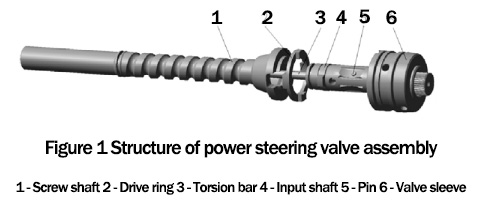
The outer circle of the input shaft and the inner hole of the valve sleeve are clearance fits so that they can turn each other when the car is steered. A deep hole is drilled in the center of the screw shaft to connect the rotary valve to the oil passage in the rear chamber of the power steering gear. During assembly, the bolt on the housing is adjusted until the axial position of the screw shaft, drive ring, and valve sleeve is fixed. The bottom of the screw shaft is pressed with a carburized and hardened plug block to reduce the friction between the head of the adjusting bolt and the plug block and increase the wear resistance to improve the service life; the valve sleeve is equipped with a flat needle roller bearing between the valve body and the valve sleeve, which can withstand the axial force and make the valve sleeve rotate lightly and reduce the hand force required for steering.
The structure of the drive ring is shown in Figure 2, there are 2 convex keys on the left and right end faces respectively, and the mutual perpendicularity requirement is generally 0.10.

The two convex keys on the left side of the drive ring are connected to the angle limit slot of the screw shaft, and the two convex keys on the right side are connected to the slot of the valve sleeve, thus forming a rigid connection between the valve sleeve and the screw shaft. The steering wheel is connected to the input shaft of the steering rack in the form of a spline through the steering rack, and the input shaft is rotated at a certain angle relative to the screw shaft during steering.
2 Turning Valve Working Principle
The rotary valve is the directional control valve of the hydraulic transmission part of the power steering rack. As shown in Figure 3, its main part consists of a valve sleeve and valve spool. The sleeve and spool have radially machined inlet and return ports on the outer circle, the axial oil groove in the inner hole of the sleeve is milled and ground with the convex key on the outer circle of the input shaft, and the oil groove is slightly wider than the convex key, leaving a gap to ensure that the upper and lower cavities in the middle position are connected to each other, so this structure is called the normal flow type rotary valve.

When the vehicle is driving in a straight line, the driver does not apply torque to the steering wheel. In this state, the input shaft spool is in the middle position relative to the screw shaft and the valve sleeve, and the torsion bar does not produce torque or angular displacement. The hydraulic oil delivered by the steering oil pump enters the valve sleeve and spool from the inlet hole on the steering valve body, and then enters the lower and upper chambers of the steering housing cylinder from both sides (the gap between the convex key of the spool and the oil groove of the valve sleeve), and returns to the oil reservoir through the valve sleeve on the steering valve and the return hole and return pipe of the valve body. The oil flows to the upper and lower cavities of the steering cylinder at the same time with the same flow rate, there is no pressure difference, so the oil pressure on both sides of the rack piston is equal, with no power assist, and steering is produced, it stays in the middle position and the car keeps driving in a straight line.
When the steering wheel is turned, the input shaft rotates relative to the screw shaft, which means the spool produces angular displacement relative to the valve sleeve. The gap between the spool cam key and the oil groove side of the valve sleeve will gradually become larger, and the oil overflow area will gradually increase; at the same time, the gap on the other side will gradually become smaller, and accordingly, the overflow area will gradually decrease until it is completely closed. Through the upper and lower oil chamber pressure difference between the two ends of the rack piston steering assistance, push the rack piston in the housing cylinder to do linear motion and through the rack fan drive vice drive the rocker arm shaft rotation, so as to achieve steering.
When the driver has steered the vehicle to a certain angle and stopped applying torque to the steering wheel, the input shaft connected with the steering gear will stop rotating simultaneously. The piston of the rack and pinion will continue to move linearly in the housing cylinder under the action of the pressure difference between the upper and lower chambers, and the screw nut will make the screw shaft drive the valve sleeve to continue to rotate until the relative position of the valve sleeve and the input shaft spool returns from the state of angular displacement when turning to the state when the vehicle is driving straight. At this time, the spool key and the valve sleeve oil groove are in the middle position again, the gap and overflow area on both sides are equal, the pressure difference between the upper and lower cavities of the steering cylinder disappears, and the rack piston loses power, it is stabilized in a certain position, and the vehicle continues to turn in the established turning angle. When the driver turns the steering wheel to drive straight, the relative position of the valve sleeve and the valve spool will be different from that of the vehicle when it turns in the opposite direction for a short time. The relative position of the valve sleeve and the valve spool is the same as that of the vehicle when turning in the opposite direction for a short period of time, producing a certain angular displacement, and then restoring Then the vehicle will return to the straight driving state.
3 Failure analysis and maintenance
Although each part of the steering rack is strictly controlled in the process of processing and testing, the quality of the steering control valve or the steering gear assembly may still be affected during the bench test. Although the quality of the steering parts is strictly controlled during the processing and testing process, some of the test items may still fail during the bench test of the steering control valve or steering assembly. In addition, many failures of the power steering gear in use are also related to the valve. In addition, a lot of faults that occur in the process of power steering are also related to the valve, and the specific causes of faults and maintenance measures are analyzed as follows. The specific causes and maintenance measures are analyzed as follows.
(1) Failure of bench test
(1.1) The force characteristic curve is not smooth
Before the steering valve is assembled into the steering assembly, the performance test must be conducted according to the bench test method of automotive power steering valve assembly. When testing the force characteristic curve, it often appears that the curve is not smooth. Such a valve can cause sudden changes in torque during steering, which can feel shaky and uneven and affect the driver's road feel. The sudden change of torque during the test will produce a force characteristic curve that is not smooth, generally, due to the interference between the spool and the sleeve in the process of mutual rotation, this interference may be the friction between the two with two small clearance or poor roundness caused by excessive friction, or it may be the valve body assembly in the plane needle roller bearing because of improper assembly and damage, resulting in the sleeve rolling inflexible. The solution is to pay attention to detect the coaxiality of the bore and outer circle of the valve sleeve, improve the surface quality and roundness of the outer surface of the spool and the bore of the valve sleeve, and select the appropriate fit clearance for the valve sleeve spool grouping option to avoid interference. In addition, the screw shaft and the input shaft should be assembled to ensure a high coaxiality, so that the flat bearing at the bottom of the valve body and the valve sleeve end contact closely and evenly, and flexibly rotation.
(1.2) Curve symmetry exceeded
Curve symmetry is a very important testing index during the rotary valve bench test. The test proves that when the symmetry of the curve is lower than 90%, the driver can feel the difference in the size of the steering force between the left and right directions when steering. The symmetry of the curve is determined by the quality of the equalization of the spool key and sleeve groove and the accuracy of the valve assembly alignment. The dividing quality of the sleeve groove is ensured by the powder metallurgy molding tooling, and the spool key is machined by a milling machine with an indexing head or a CNC milling machine with an indexing function, and the indexing accuracy is the main influencing factor. The shape and width of the key edge have the greatest influence on the symmetry of the curve. When the rotary valve is assembled, the input shaft spool and sleeve are first clamped on the alignment machine with a special alignment jig to determine their relative angular positions before drilling and pressing the pin. The accuracy of the alignment determines the size of the "pre-opening gap" on both sides of the valve sleeve and spool oil port, which also directly affects the curve symmetry. The manufacturing accuracy of the alignment jig and the wear of the positioning elements during use are all influencing factors.
For a small number of symmetry is not the too serious difference in the rotary valve, can be directed by the bench test operator with sand bars in the corresponding edge part of the manual grinding, and then re-test, until qualified. In the case of mechanically aligned rotary valves, the test failed rotary valve must be pressed out of the pin to re-align and then drill and press the pin again, which is not only a tedious process but also cannot guarantee that the test will be passed again. The drive ring shown in Figure 2 has two sets of locating tabs 90° apart for connecting the sleeve to the spool. Several different sizes of drive rings can be ordered, the left end key is used as the reference, and the right end key is designed and manufactured with different inclination angles, and grouped in both directions with a certain drop. If there is a curve symmetry overrun, the drive ring can be reworked by replacing it. The relative angle between the screw shaft and the input shaft spool has been fixed by the torsion bar pressure pin, and the relative angle between the valve sleeve and the screw shaft can be changed by replacing different groups of drive rings, thus changing the relative angle between the valve sleeve and the spool and thus improving the curve symmetry. Also, the process route can be changed by replacing mechanical alignment with hydraulic alignment, the main process is manual loading - alignment and performance test - drilling and reaming - press pin --Again performance test --Manual unloading. All processes outside of loading and unloading can be designed to be done automatically, thus improving accuracy and efficiency.
(1.3 )Torque Overload
The driver's steering feel is determined by the input torque value of the steering gear under a certain pressure. If the torque value is too large, the driver will feel heavy steering, and if the torque value is too small, the driver's "road feel" will not be obvious. In addition, the size and shape accuracy of the torsion bar is very important, the external dimensions should be strictly controlled during the machining process, and the heat treatment process is also very critical. In addition, the size of the rotary valve "pre-open gap" also affects the torque value, too small spool flange width will increase the steering torque.
(1.4) Internal leakage
The internal leakage in the bench test may be due to excessive clearance between the valve sleeve and the spool grouping, excessive error in the size of the sealing groove on the outer circle of the valve sleeve and the input shaft, or the seal ring being scratched during the assembly process, and these possibilities of failure should be investigated one by one.
(2) Failure of steering gear during use
(2.1) Power steering rack oil leakage
The main reason is that the seal between the valve body bore and the input shaft outer circle is worn out, which should be replaced after disassembling the steering gear valve body.
(2.2) Heavy steering
The seal between the input shaft outer circle and the oil passage of the screw shaft inner hole, the seal between the screw shaft tail outer circle and the rack piston inner hole, or the O-ring on the valve sleeve outer circle is worn or scratched by the impurities in the oil will cause heavy steering, and the O-ring should be replaced after disassembling the steering gear. In addition, the valve spool and valve sleeve are stuck because of oil impurities, and the flat needle roller bearing between the valve sleeve and the valve body can cause heavy steering on the left and right side if it is damaged, which should be replaced with new oil after troubleshooting.
(3) Automatic wheel runout
The reason for this fault related to the rotary valve is that the torsion bar is subjected to plastic deformation by an external force, that is, the torsion bar produces irrecoverable angular displacement at both ends, resulting in the relative position of the input shaft spool and the valve sleeve in a state similar to the position of the vehicle when turning in a straight line. The torsion bar is used to determine the centering position of the spool and sleeve during the assembly of the steering. Once the deformation occurs, not only will the direction run off, but the left and right steering torque will also be asymmetrical and the feel will become worse. The method of disassembling the steering gear and steering control valve to correct the torsion bar is actually not feasible, because the method of using a wrench to deform the torsion bar in the opposite direction and recalibrating the torsion bar by visual inspection is far from being accurate enough to meet the requirements of valve alignment, and the valve has an angle limiting device, which can only be rotated by 7° at most, so it may not be able to produce enough plastic deformation of the torsion bar. The rotary valve assembly should be disassembled and the torsion bar should be replaced, and the pin should be re-centered and tested on a bench before it can be used again.
4 Conclusion
As a key component of the power steering, the steering control valve has a complex structure and is closely related to The steering performance of vehicle driving is closely related. By analyzing the structure and working principle of the power steering valve and working principle of power steering valve, and analyzing the faults related to the steering valve during the bench test of the steering assembly and The analysis and maintenance measures are proposed for the production and maintenance of steering gears. The analysis of the steering valve structure and operating principle, and the analysis of the valve-related faults in the steering assembly bench test and in the process of installation and use.
References
[1] Analysis and improvement of symmetry of power steering rotary valve force characteristics[J]. Chen Cheng,Gu Jin. Machine Tools and Hydraulics. 2019(10)
[2]The effect of power steering rotary valve outer runout on static characteristics[J]. Chen C,Gu J. Machine Tools and Hydraulics. 2013(17)
[3] Analysis and troubleshooting of common faults of power steering system[J]. Wang Xiuping,Yao Chunyan. Agricultural machinery use and maintenance. 2013(07)
[4] Analysis of heavy steering failure of automobile [J]. Li Xiangdong,Shen Xiaozhong. Lubrication and sealing. 2006(11)
(We do not share your data with anybody, and only use it for its intended purpose)
The Previous Articles:
What Is Rack and Pinion Bushing? How To Tell If Rack and Pinion Bushings Are Bad?
Why Steering Rack Makes Noise When Turning?
How To Rebuild A Steering Rack?
What Is A Rotary Valve Power Steering Rack?
Rack And Pinion System Vs Power Steering System: What Are The Differences?
Power Steering Rack Market Analysis Report (Japan Market)
What Causes Steering Rack to Go Bad?
Design Of Car Rack And Pinion Steering Racks
What Is The Intelligent Steering Rack Used By VW, Toyota, Honda And Renault?
Leave A Comment