I wonder if you have noticed that the two steering wheels in the steering system do not have the same deflection angle when the car is steering, why is this? And what kind of relationship do they have?
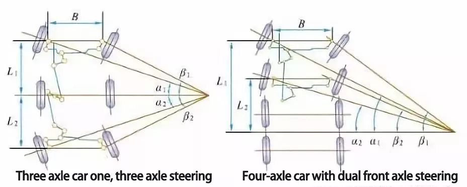
When a car is steering, in order to avoid additional resistance caused by the wheels sliding relative to the ground and reduce tire wear, the steering system is required to ensure that all wheels are purely rolling, that is, the extension lines of all-wheel axes should intersect at one point.
1 Deflection angle of the steering system
The following diagram shows the relationship between the deflection angle of the steering wheels when the car is steered.
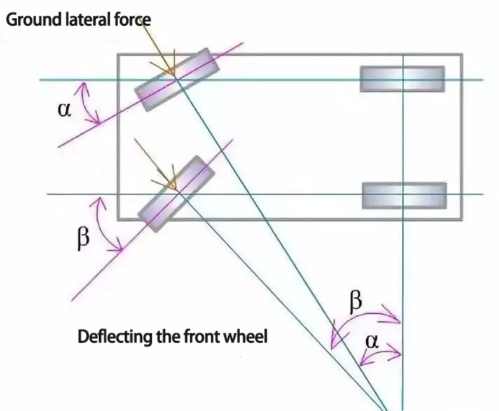
Where α and β are the deflection angles of the inner and outer steering wheels respectively, B is the distance between the intersection of the main pin axis and the ground on both sides; L is the wheelbase of the car. They have the following relationship with each other.
cotα = cotβ + B/L
This is the ideal relationship between the deflection angle of the steering wheels on both sides. It is determined by the structure type of steering transmission mechanism.
Steering System Ratio
The larger the value, the greater the amplification of the steering system to the driver's maneuvering force, and the lighter the steering, but the steering sensitivity will be reduced.
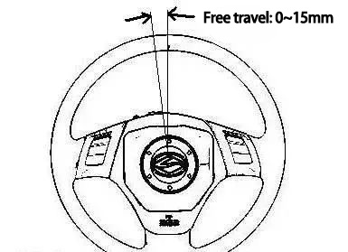
When we turn the steering wheel, we will feel an empty journey, and the angular travel of the steering wheel in the idling stage is called the free travel of the steering wheel.
The free travel of the steering wheel is good for easing the impact of the road and avoiding excessive tension of the driver, but it should not be too large, otherwise, the steering sensitivity will be reduced. The general steering wheel free travel is not more than 10 degrees or the steering wheel circumference arc length 0 ~ 15mm.
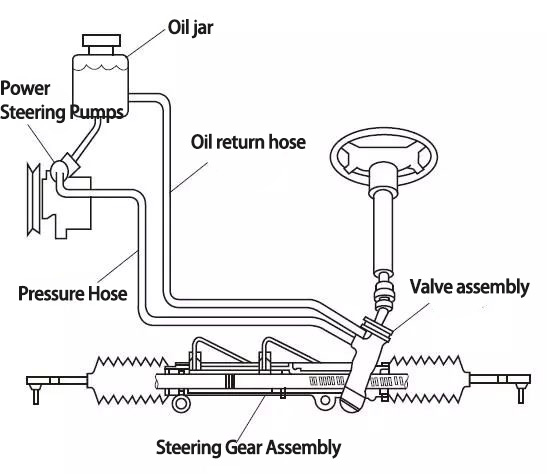
2 Working principles of hydraulic power-assisted rack and pinion steering
When the hydraulic power-assisted rack and pinion steering is not hydraulically assisted, the working principle of the steering gear is sketched as follows ▼

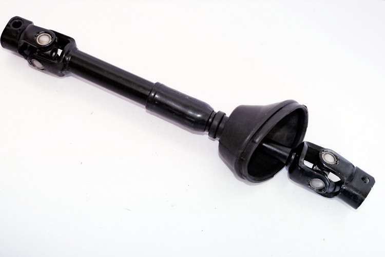
The torsional force exerted on the steering wheel is transmitted to the steering gear active gear (steering control valve gear) through the intermediate shaft, because the teeth of the active gear (steering control valve gear teeth) are in mesh with the rack gear teeth, converting the torsional force transmitted from the steering wheel into linear force of the rack, which makes the rack move from side to side. The linear force is transmitted to the inner and outer steering cross-ties and then to the steering knuckle, which reverses the direction of the wheels.
The rack and pinion steering system with hydraulic power is shown in the figure below. It is a mechanical rack and pinion steering system with a steering power cylinder and steering control valve designed to form an integral power steering system. The piston of the power cylinder and the rack and pinion are made into one unit, and the power cylinder is divided into two chambers.
The structure of the steering control valve is shown in the figure below ▼

When the steering wheel is not turned, the steering control valve is in the middle position, and the oil from the power steering pump assembly flows into the valve chamber from the steering control valve inlet. Since the steering control valve is in the middle position, the left and right chambers of the power cylinder are connected, and the oil flows back to the oil pot from the steering control valve outlet, so the hydraulic booster does not work.
Steering control valve principle.
The control valve is located in the middle ▼

Steering control valve principle
Control valve left ▼
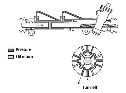
Control valve left
Control valve right turn ▼
Control valve right turn
When turning the steering wheel, the steering shaft together with the steering control valve spool rotates, because the steering resistance from the steering knuckle arm, the power cylinder piston, and rack can not move temporarily, so the steering control valve gear can not rotate together with the steering shaft temporarily.
Thus, the torque transmitted from the steering shaft to the steering control valve gear can only cause a small twisting deformation of the torsion bar inside the steering control valve, so that the steering shaft together with the steering control valve spool can produce a small rotation relative to the steering control valve gear so that the steering control valve makes one side of the power cylinder become a high-pressure oil inlet chamber, and the other side becomes a low-pressure oil return chamber. The high hydraulic force acting on the power cylinder piston helps the steering control gear to force the steering rack to one side. At the same time, the steering control gear itself begins to rotate in the same direction as the steering shaft.
As long as the steering wheel continues to rotate, the torsional deformation of the torsion bar remains constant, and the steering control valve’s booster action remains the same. Once the steering wheel stops rotating, the high hydraulic force in one side of the power cylinder continues to exist temporarily, causing the steering control valve gear to continue to rotate, reducing the torsional deformation of the torsion bar until the torsion bar returns to its natural state. The steering control valve returns to the middle position, and the left and right sides of the power cylinder are connected so that the hydraulic power does not work. At this point, the steering wheel is parked in a certain position and does not move, the wheel angle remains certain. If the steering wheel is turned again, the hydraulic power assist will work again.
The hydraulic pressure on the piston of the power cylinder is converted into linear force, which helps the rack move from side to side and push the steering knuckle and wheel rotation through the steering cross lever.
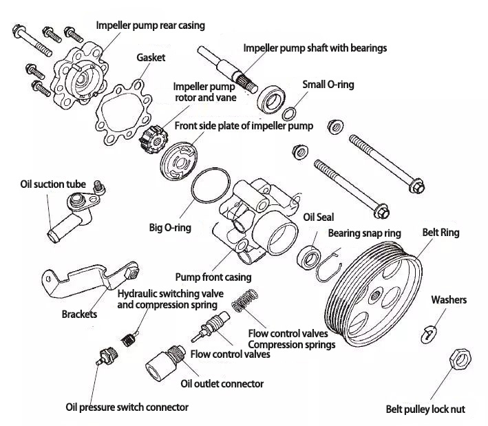
3 Working principles of power steering pump assembly
The common form of power steering pump is the vane type and its working principle is shown in the figure below ▼

The engine torque is transmitted to the belt of the power steering pump assembly through the drive belt and drives the shaft and rotor of the power steering pump assembly to rotate. The vane mounted on the rotor is thrown out due to the centrifugal force of rotation and rotates against the inner wall of the pump ring (pump rear casing), which draws the steering fluid from the oil pot into the pump cavity and presses the steering fluid into the steering gear through the flow control valve to provide hydraulic power to the steering gear. The flow control valve regulates the flow of fluid into the steering gear according to the pressure of the fluid in the system, so as to adjust the pressure of the fluid in the system and prevent the hydraulic pressure of the system from being too high.
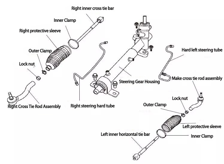
4. Steering rack exploded view
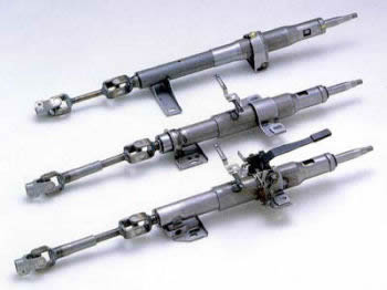
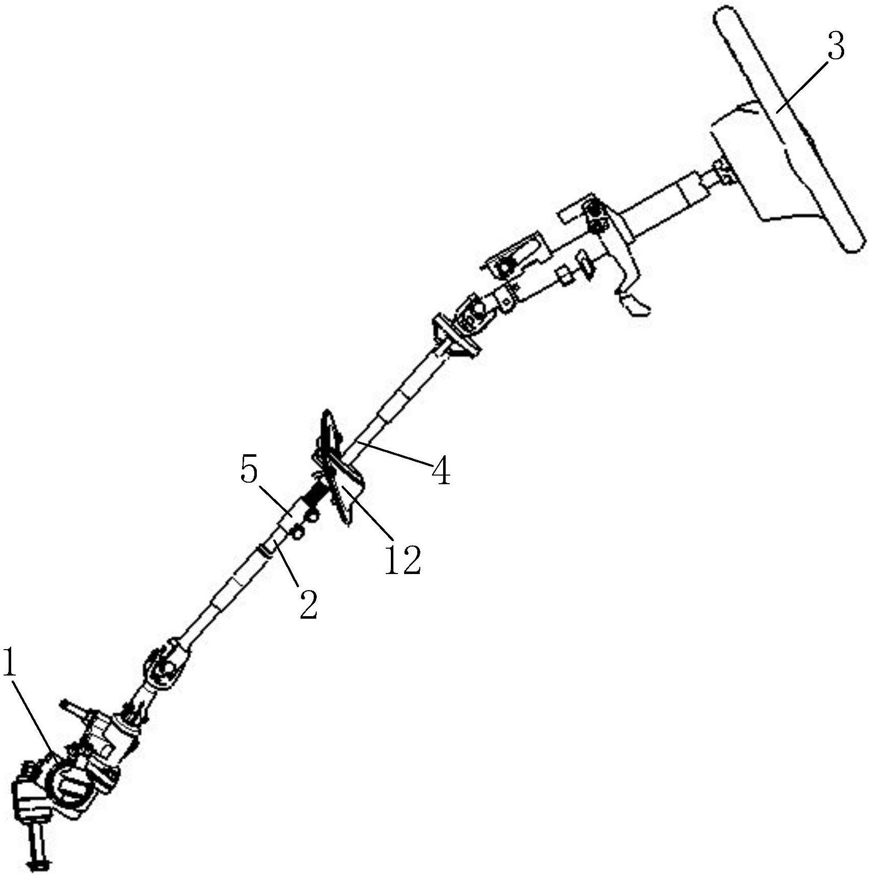
Steering System Component Location Diagram ▼

Steering Column and Steering Gear Installation Diagram ▼

Exploded view of steering gear ▼
Exploded View of Power Steering Pump ▼
Content source.
<The perspective view explains the car structure. Principle and Disassembly>Chemical Industry Press Editor-in-Chief: Yu Haidong
(We do not share your data with anybody, and only use it for its intended purpose)
The Previous Articles:
What Is Rack and Pinion Bushing? How To Tell If Rack and Pinion Bushings Are Bad?
Why Steering Rack Makes Noise When Turning?
How To Rebuild A Steering Rack?
What Is A Rotary Valve Power Steering Rack?
Rack And Pinion System Vs Power Steering System: What Are The Differences?
Power Steering Rack Market Analysis Report (Japan Market)
What Causes Steering Rack to Go Bad?
Design Of Car Rack And Pinion Steering Racks
What Is The Intelligent Steering Rack Used By VW, Toyota, Honda And Renault?
Leave A Comment